The same current flows in each resistor, the voltages across them are typically different, where V = V1 + V2 + V3 which leads to the equivalent resistance formula
Req = R1 + R2 + R3
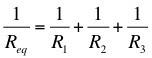
The potential difference across each resistor is the same, but the currents through them are typically different, where I = I1 + I2 + I3. This lead to the equivalent resistance formula,
Note that both of the diagrams below represent resistors in parallel.

Some circuits can be analysed as combinations of series and parallel circuits. In the circuit below R2 and R3 are in parallel, their equivalent resistance is then in series with R1.
Note that it is not possible to represent all circuits as combinations of series and parallel elements, this is most obvious in many cases where there is more than one battery in the circuit, see example below. To analyse this type of circuit we must use Kirchhoff's Laws.
Got mole problems? Call Avogadro at 602-1023.
Dr. C. L. Davis
Physics Department
University of Louisville
email: c.l.davis@louisville.edu